Removing a Large Engine While Still in the Water
This is Part 2 in our adventures in repowering our sailboat with electric drive. Based on questions and feedback, this is going to be long. I try to keep the detail relevant to people who may want to do this themselves. We are happy to answer any questions that arise.
Part 1, "Towards Electric Drive" is here.
Part 3. "Actual Engine Removal" is here.
The Problem(s)
The Planning
The Execution
Most of the time, we get to stand on the shoulders of sailors that did something before we did. Most sailors don't have a Large Diesel Engine they are trying to remove in an unconventional way. There is some information out there on removing engines from boats, but they all involve smaller engines or a boatyard and large crane.
We had a few problems to solve. Working on your house while you live in it is always a tile puzzle game. Even more so on a boat. The overarching problem is: we need to lift Large Diesel Engine while still at dock in the marina. "Why not do that in a yard and hire a crane?" I'm glad you asked. There is no boatyard reasonably nearby that can fit our boat. First we would need to motor to a yard, which would be the easiest part of doing this in a yard. The nearest DIY boatyard is 30 miles away by water, and that's the icky one. Then we would need to prep the motor for removal while not having a place to stay and our workshop being over 40 miles away. Too much logistics, too much churn will occur.
I have owned and worked on this boat for over five years now. There are always nasty surprises lurking, resulting in scope creep and delays. Oh look, here's an odd bolt that needs to be removed and we don't have that exact large wrench.Oh, there's rot here that we need to repair before we can proceed.
Part 1, "Towards Electric Drive" is here.
Part 3. "Actual Engine Removal" is here.
The Problem(s)
The Planning
The Execution
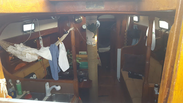
The Problem(s)
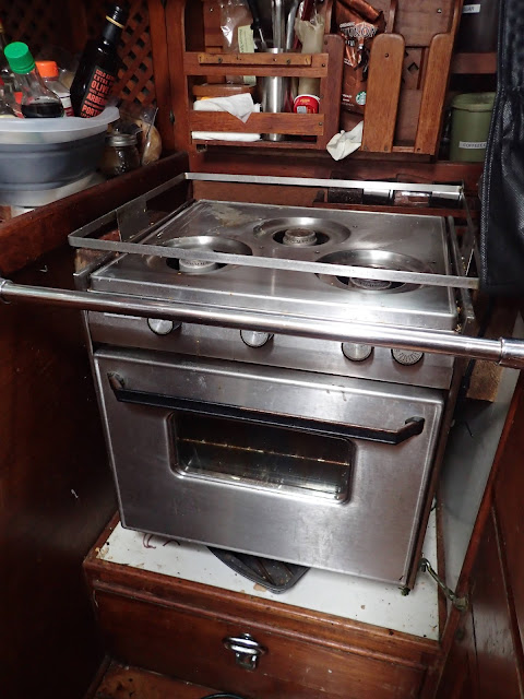
 |
| All of that is coming out. All of it. |
We had a few problems to solve. Working on your house while you live in it is always a tile puzzle game. Even more so on a boat. The overarching problem is: we need to lift Large Diesel Engine while still at dock in the marina. "Why not do that in a yard and hire a crane?" I'm glad you asked. There is no boatyard reasonably nearby that can fit our boat. First we would need to motor to a yard, which would be the easiest part of doing this in a yard. The nearest DIY boatyard is 30 miles away by water, and that's the icky one. Then we would need to prep the motor for removal while not having a place to stay and our workshop being over 40 miles away. Too much logistics, too much churn will occur.
I have owned and worked on this boat for over five years now. There are always nasty surprises lurking, resulting in scope creep and delays. Oh look, here's an odd bolt that needs to be removed and we don't have that exact large wrench.Oh, there's rot here that we need to repair before we can proceed.
This translates to money. A lot of money when burning yard time. Then we would need to be put in the water and towed into our home slip. There is a lot of work to be done before we put in the electric motor. While installing the electric motor could be a drop-in process, we want our engine compartment to be spotless and neat before putting in the new hotness. Boat tows are also expensive. Therefore it is financially reasonable to do this on our timeline.
The next problem is how to transfer Large Diesel Engine from the boat to the dock. This engine weighs a little over 1100 pounds (engine: 874 pounds; flywheel: 87 pounds; transmission: 150 pounds). It is actually pretty easy to lift the engine. Disassembly is not on the table for a few reasons. Foremost, the buyer requested that I leave the head and injectors intact. Well, shit.
I removed and rebuilt this transmission in 2016, so I have practical experience with the dynamics of the Remove Heavy Thing From Cramped Space process. It was some of the most awful boat yoga in my life. I never want to relive that. "Just get a crane." A crane presents a lot of other logistics and timing issues. We even looked into renting a micro-crane, but they won't fit on the dock, even if we could find one.
So, lifting the engine... There's this engine up in the air and the boat is floating under it. Floating, as in the boat will shift because of wind and waves. There are slow and fast ferries which kick out a bunch of wake; the fast ferry in particular generates a lot of wake. Winds will also rock the boat. Timing and weather are considerations to be considered.
How do we get the engine onto the dock? To complicate the issue, shifting the engine towards the dock will cause the boat to heel in that direction.The engine will act as a pendulum, remaining mostly static while the boat and dock finger shift. How much will the boat heel? That is math that I don't want to try to calculate; the cost of miscalculation could be catastrophic. The shift in loads on lifting apparatus might very possibly cause breakage. Some wave action will be inevitable regardless of how strictly we time this. We need a system able to accept the independent movements of the boat and engine relevant to the dock.
Once the engine is on the dock, it can't stay there. We have to move it. And it is an uphill effort. The traction material on the dock ramps presents significant rolling resistance to various caster materials and sizes – we tried and tested various materials. No matter the tide level, the shape of the dock ramps means that we have to roll the engine up the same vertical distance, but we have to consider whether we want to deal with rolling the engine down the final ramp at high tide. I would prefer to deal with gravity only once and in one direction. Low tide it is.
The buyer of our engine lives in Sitka, Alaska. The engine needs to be safely crated for shipping. This is one of the easiest parts of this project. There is ample information on crating engines for shipping so I will skip over this.
Then we need to deliver Large Diesel Engine to the freight company. This also presents a small problem since the bed capacity for our truck is 1600 pounds, evenly distributed. Unfortunately Large Diesel Engines didn't get the memo and decided they prefer to be dense. In addition to being large, does what it says on the box, I guess. This is more of a logistics problem than an engineering problem, but planning and timing are still involved.
There are no off-the-shelf gantries that fit our boat. The weight and size of capable gantry cranes make them unreasonable. Even if there was a gantry that fit, the feet would concentrate the weight and potentially crack the deck. Weight concentration is easily mitigable. But the standard gantry design terminates at the legs and would not get us to the dock. The vertical leg blocks our progress.
Shifting the engine to the dock could be solved by a three-legged jib. The two legs allow the engine to be shifted outboard of the boat. But what happens when the engine is cantilevered over the side of the boat? I could secure the single leg to the boat and it would act as a long lever acting against the gravity on the engine. Jib car rails and sail winches are immensely strong. However, the two legs would be the fulcrum, and the engine would have a moment arm on which to exert force on the boat deck.
We are also back to the problem of an off-the-shelf jib fitting where we want/are able to put it. Our side decks are roughly eight feet wide and have compound curves, that is, both the width and height change. The load of the engine would not be strictly vertical relative to the jib (not a huge deal) and the jib would have to be set at a yaw angle in relation to the boat. This presents fit issues from where we lift the engine to where we offload since there are winches and stanchions that we need to clear. Also, jibs are expensive and the models we found lacked the capacity for this job.
So we build our own from scratch. My original idea was to build a three-legged jib using an I-beam for the gantry. We need a 16 foot beam to reach the dock. How do we support the beam so that a trolley can shift under it? Welding is outside of my skills, equipment, and timeline. I-beams are expensive and not something we can just go buy locally. The length we need necessitates custom order. A 2-ton trolley requires a 3½ inch flange I-beam, which weighs over 15 pounds per foot. And how do we carry a 16 foot, >250 pound I-beam down to the boat? These are all solvable, but outside of the problem space I want to address.
I decided on a wooden three-legged jib with an A-frame on the dock side of the boat. Using wood is well within our budget, skills, equipment, and workshop capabilities. By building an A-frame on the dock side of the gantry, we can slide the engine hoist along the beam. Supporting the beam, rather then depending the beam, makes construction easier, but adds steps to transferring the engine off the boat. A single 4x4 leg on the far side of the gantry will be sufficient for handling the loads involved, while the A-frame with 2x4 legs and crotch will prevent the beam from rolling on its long axis. Using 2x6 for the feet on the legs will distribute the loads on the deck. Securing the single leg to the jib car rail and winches will handle longitudinal loads relative to the gantry.
How much and what kind of wood do we need for this? Playing around with the wood beam calculator from Cornell University (https://courses.cit.cornell.edu/arch264/calculators/example8.1/index.html), I should be able to use two Douglas fir 2x6, through-bolted together. Through-bolting the beams causes them to act as a single beam. For an additional margin, we chose 2x8 fir as our beam material; the load capacity of wood increases by the cube of height. Of course, now I can't find that reference. But even if it is only a 300% increase, I'll take it. A strip of steel bar stock on top will distribute the point load (reducing peak PSI), prevent the chain from digging into the top of the beam, and provide a lower friction interface for sliding the engine/lift assembly along the beam. I will use a come-along to shift the load along the beam in a controlled fashion.
The next problem is how to transfer Large Diesel Engine from the boat to the dock. This engine weighs a little over 1100 pounds (engine: 874 pounds; flywheel: 87 pounds; transmission: 150 pounds). It is actually pretty easy to lift the engine. Disassembly is not on the table for a few reasons. Foremost, the buyer requested that I leave the head and injectors intact. Well, shit.
I removed and rebuilt this transmission in 2016, so I have practical experience with the dynamics of the Remove Heavy Thing From Cramped Space process. It was some of the most awful boat yoga in my life. I never want to relive that. "Just get a crane." A crane presents a lot of other logistics and timing issues. We even looked into renting a micro-crane, but they won't fit on the dock, even if we could find one.
 |
| Removing just the transmission. |
How do we get the engine onto the dock? To complicate the issue, shifting the engine towards the dock will cause the boat to heel in that direction.The engine will act as a pendulum, remaining mostly static while the boat and dock finger shift. How much will the boat heel? That is math that I don't want to try to calculate; the cost of miscalculation could be catastrophic. The shift in loads on lifting apparatus might very possibly cause breakage. Some wave action will be inevitable regardless of how strictly we time this. We need a system able to accept the independent movements of the boat and engine relevant to the dock.
Once the engine is on the dock, it can't stay there. We have to move it. And it is an uphill effort. The traction material on the dock ramps presents significant rolling resistance to various caster materials and sizes – we tried and tested various materials. No matter the tide level, the shape of the dock ramps means that we have to roll the engine up the same vertical distance, but we have to consider whether we want to deal with rolling the engine down the final ramp at high tide. I would prefer to deal with gravity only once and in one direction. Low tide it is.
The buyer of our engine lives in Sitka, Alaska. The engine needs to be safely crated for shipping. This is one of the easiest parts of this project. There is ample information on crating engines for shipping so I will skip over this.
Then we need to deliver Large Diesel Engine to the freight company. This also presents a small problem since the bed capacity for our truck is 1600 pounds, evenly distributed. Unfortunately Large Diesel Engines didn't get the memo and decided they prefer to be dense. In addition to being large, does what it says on the box, I guess. This is more of a logistics problem than an engineering problem, but planning and timing are still involved.
The Planning
So much agonizing. "Just use the boom and halyard!" I refer you back to the 1100 pound figure. The cost of breaking my boom or separating a halyard could be catastrophic loss of the boat. Also, the boom lacks the height for the engine to clear the cockpit coaming. The right tools for this lifting job are a gantry and a 2-ton chainfall hoist. The chainfall uses a reduction gear driven by a continuous loop of chain to provide movement on another chain attached to a hook. A chainfall provides approximately a 4000:1 mechanical advantage, that is 4000 units of drive chain movement translates to 1 unit of movement of the lift hook. The manual operation allows precise control of the lifting. |
| Chainfall action shot. |
There are no off-the-shelf gantries that fit our boat. The weight and size of capable gantry cranes make them unreasonable. Even if there was a gantry that fit, the feet would concentrate the weight and potentially crack the deck. Weight concentration is easily mitigable. But the standard gantry design terminates at the legs and would not get us to the dock. The vertical leg blocks our progress.
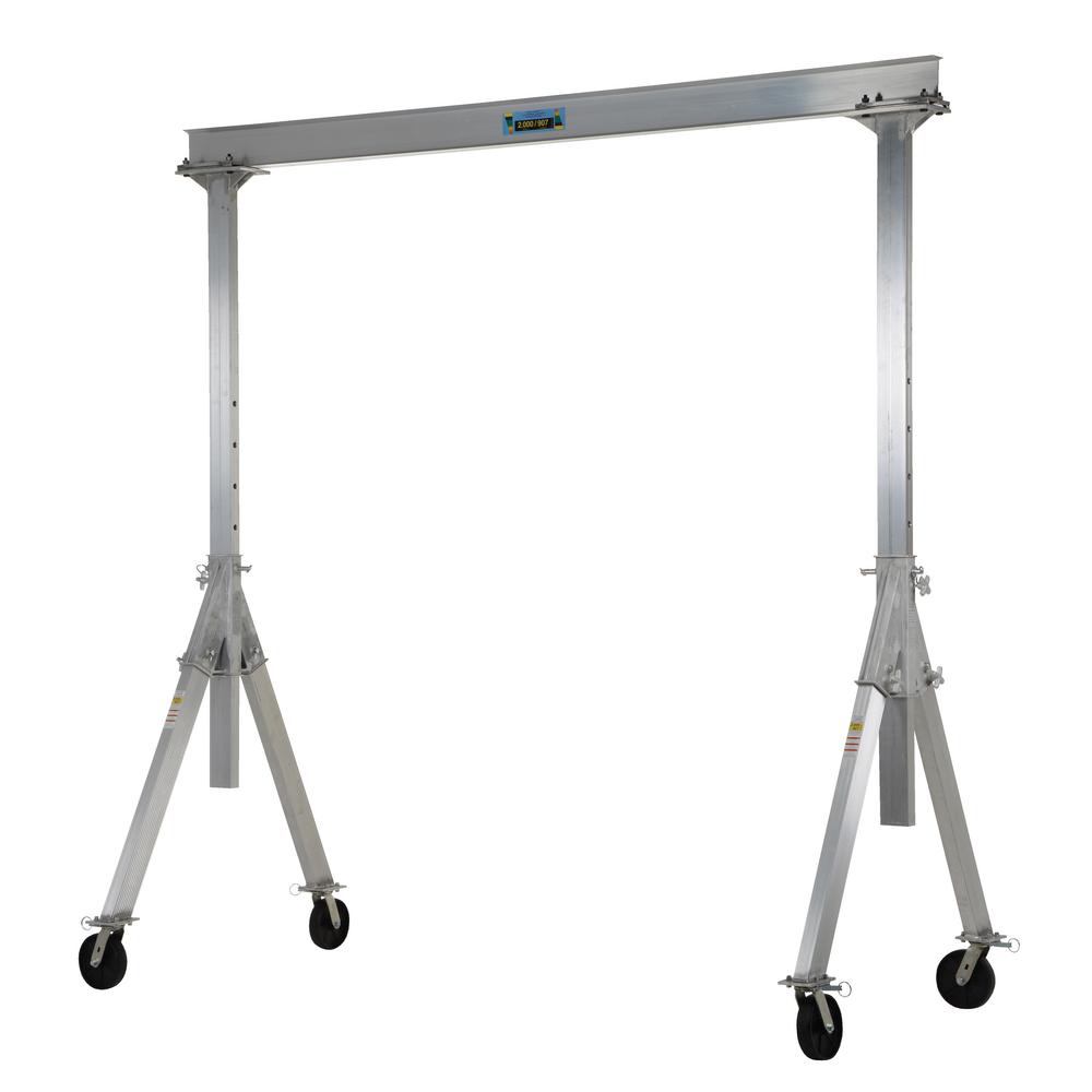 |
| An adjustable gantry |
Shifting the engine to the dock could be solved by a three-legged jib. The two legs allow the engine to be shifted outboard of the boat. But what happens when the engine is cantilevered over the side of the boat? I could secure the single leg to the boat and it would act as a long lever acting against the gravity on the engine. Jib car rails and sail winches are immensely strong. However, the two legs would be the fulcrum, and the engine would have a moment arm on which to exert force on the boat deck.
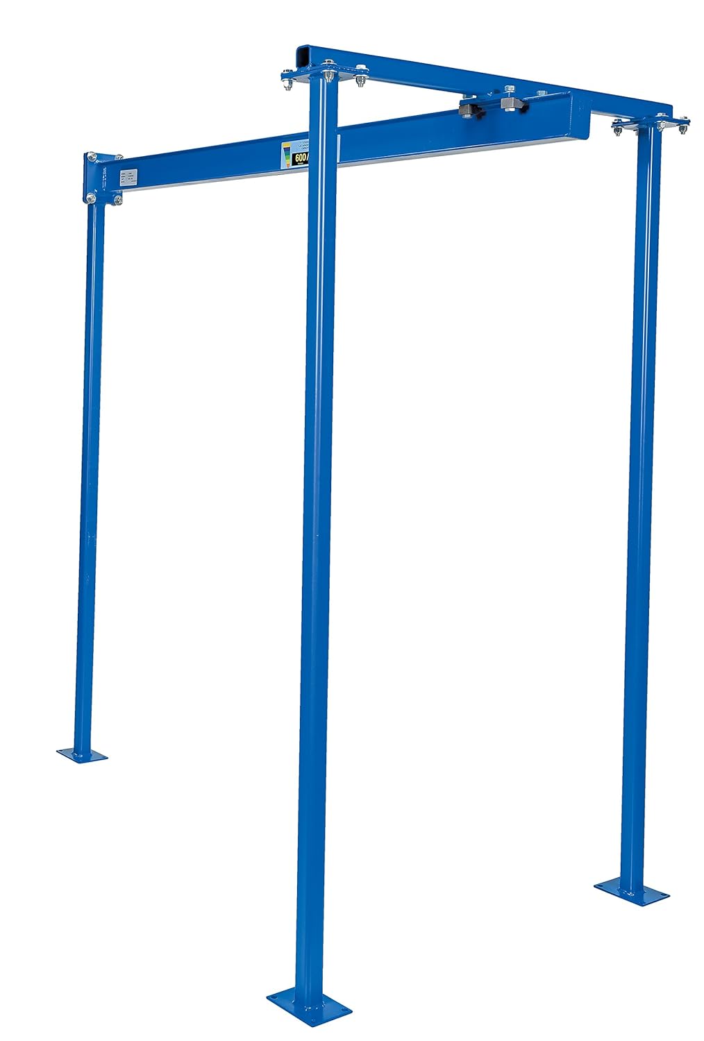 |
| Three-legged jib |
We are also back to the problem of an off-the-shelf jib fitting where we want/are able to put it. Our side decks are roughly eight feet wide and have compound curves, that is, both the width and height change. The load of the engine would not be strictly vertical relative to the jib (not a huge deal) and the jib would have to be set at a yaw angle in relation to the boat. This presents fit issues from where we lift the engine to where we offload since there are winches and stanchions that we need to clear. Also, jibs are expensive and the models we found lacked the capacity for this job.
So we build our own from scratch. My original idea was to build a three-legged jib using an I-beam for the gantry. We need a 16 foot beam to reach the dock. How do we support the beam so that a trolley can shift under it? Welding is outside of my skills, equipment, and timeline. I-beams are expensive and not something we can just go buy locally. The length we need necessitates custom order. A 2-ton trolley requires a 3½ inch flange I-beam, which weighs over 15 pounds per foot. And how do we carry a 16 foot, >250 pound I-beam down to the boat? These are all solvable, but outside of the problem space I want to address.
I decided on a wooden three-legged jib with an A-frame on the dock side of the boat. Using wood is well within our budget, skills, equipment, and workshop capabilities. By building an A-frame on the dock side of the gantry, we can slide the engine hoist along the beam. Supporting the beam, rather then depending the beam, makes construction easier, but adds steps to transferring the engine off the boat. A single 4x4 leg on the far side of the gantry will be sufficient for handling the loads involved, while the A-frame with 2x4 legs and crotch will prevent the beam from rolling on its long axis. Using 2x6 for the feet on the legs will distribute the loads on the deck. Securing the single leg to the jib car rail and winches will handle longitudinal loads relative to the gantry.
How much and what kind of wood do we need for this? Playing around with the wood beam calculator from Cornell University (https://courses.cit.cornell.edu/arch264/calculators/example8.1/index.html), I should be able to use two Douglas fir 2x6, through-bolted together. Through-bolting the beams causes them to act as a single beam. For an additional margin, we chose 2x8 fir as our beam material; the load capacity of wood increases by the cube of height. Of course, now I can't find that reference. But even if it is only a 300% increase, I'll take it. A strip of steel bar stock on top will distribute the point load (reducing peak PSI), prevent the chain from digging into the top of the beam, and provide a lower friction interface for sliding the engine/lift assembly along the beam. I will use a come-along to shift the load along the beam in a controlled fashion.
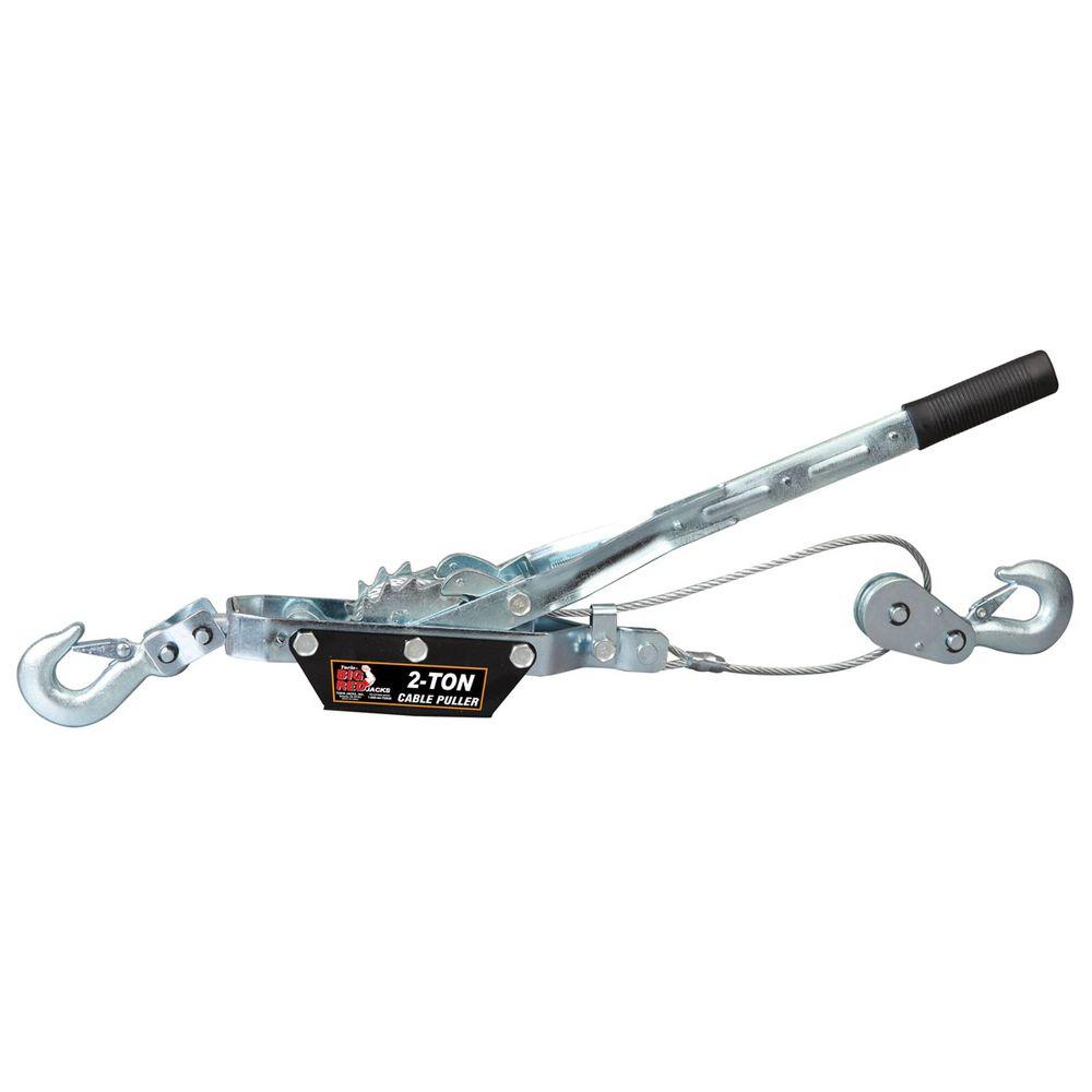 |
| A come-along |
The boat leg will have a three-sided "cup" at the top to receive the beam and lock into place. By through-bolting the beam and cup, the beam will be locked from longitudinal movement, but can pivot slightly when the boat moves fore and aft. Some hefty knees (diagonal braces) help assure longitudinal rigidity.
The A-frame is a crotch that supports the beam to keep it from rotating on its long axis (roll), but allows it shift slightly from side to side (yaw) when boat shifts in the slip. The A-frame will have knees to help frame remain upright during setup.
 |
| Single leg with three-sided cup to hold the beam. |
The A-frame is a crotch that supports the beam to keep it from rotating on its long axis (roll), but allows it shift slightly from side to side (yaw) when boat shifts in the slip. The A-frame will have knees to help frame remain upright during setup.
 |
| A-frame crotch detail. "Dat gap tho." The gap is deliberate. The knee is only there to keep the A-frame vertical while allowing us to walk on the deck around the A-frame. |
To recap, the beam is allowed to shift 1½ inches total side to side at the A-frame. There is a leg on the far side of the boat which locks the beam longitudinally and serves as a yaw pivot; at the far dock end, the beam can swing through an arc of about six total inches.
Why all this movement allowance? The boat will move pitch, yaw, roll, and move fore and aft, regardless (and because of) our efforts. When we shift the engine away from the centerline, the boat will start to heel (roll). The A-frame is already a bunch of engineering. It is there to provide roll control for the gantry beam. I want to avoid overbuilding the A-frame when there are easier ways. So a third leg on the dock gets set after we start shifting the engine, but before the boat heels too much. The third leg on the dock takes the vertical load, greatly reducing the dependency on the A-frame for holding the engine. Ideally, when the dock leg is set, there will be almost no load on the A-frame unless the beam tries to roll. The A-frame is well-built to handle this.
The dock leg is going to be subject to movement. The scary part is longitudinal movement of the boat, since too much movement could rip the beam out of the dock side cup. We will allow some lateral movement of the boat by using a single through-bolt in the beam and dock leg. The dock leg is there for vertical loading only and this design should be ample.
The dock leg is going to be subject to movement. The scary part is longitudinal movement of the boat, since too much movement could rip the beam out of the dock side cup. We will allow some lateral movement of the boat by using a single through-bolt in the beam and dock leg. The dock leg is there for vertical loading only and this design should be ample.
 |
| Test of the full gantry. Notice the beam is not yet fully in the cup. That is also deliberate. |
Until it is time for the dock leg to hold its share of the load, it floats in the air, depending from the beam and remains plumb. This allows the boat to shift naturally in the slip and applies no stress to the beam-leg joint. The plans for this operation are 45 minutes from the time the engine is at maximum height until the engine is safely in its cradle on the dock. <retrospective chuckles>
Here's a video of the assembly process.
The A-frame and leg were positioned on deck, temporarily secured with paracord, and we used the topping lift to hoist the beam into place. Emily operated the winch and I only had to provide small inputs to slot home the beam. I got the easy job. Later, we secured the frame and leg using 3000 pound capacity ratchet straps.
The first test of the gantry was to lift the binnacle out of the cockpit. This is an awkward component and weighs around 100 pounds. Fortunately, it has a convenient lifting point. This went well and we were buoyed by that early success.
Using the chainfall, we applied slow lifting force to the cockpit sole and it eventually popped free. Round 2 win!
Let's try for a Round 3 consecutive victory, and something heavier. This is a 3kW diesel generator that ran when I sea-trialed the boat. And then I never used it again. I was unable to reach all of the mounts for the generator so they would just need to be ripped free. No loss there; they were rotted anyway.
This post is getting unwieldy and starting to cause Javascript errors in the Blogger interface, so I will cut this off here. I promise: the main event will follow very soon.
The Execution
We built the gantry at our workshop using measurements and modeling taken from the boat. This was a huge proof-of-concept of our ability to take to the shop some accurate measurements and a little AutoCAD, build something remotely, and have it assemble on-site as expected. We will cover our modeling tools and process in much greater detail in a later post and when I have refined it into something that can be explained vaguely comprehensibly.Here's a video of the assembly process.
The A-frame and leg were positioned on deck, temporarily secured with paracord, and we used the topping lift to hoist the beam into place. Emily operated the winch and I only had to provide small inputs to slot home the beam. I got the easy job. Later, we secured the frame and leg using 3000 pound capacity ratchet straps.
None of us is as smart as all of us.
The assembled gantry was the first time any of our four mechanical engineering neighbors got to see the implementation. Three of them are from Colorado School of Mines and all of the engineers' career credentials are seriously impressive. If they said I needed to swallow some rusty spikes to make this work, I would do it. Upon their review, they suggested we add additional knee material on the boat leg. Specifically, make the knee as large as possible using plywood rather than dimensional lumber. Why plywood? It would allow the beam to yaw without damaging the attachment points, but provide rigidity and stability exactly in the axis we need. We absolutely implemented their suggestions.The first test of the gantry was to lift the binnacle out of the cockpit. This is an awkward component and weighs around 100 pounds. Fortunately, it has a convenient lifting point. This went well and we were buoyed by that early success.
 |
| We have liftoff! |
Onto removing the cockpit sole! This thing is robust (read: "heavy"). Also, the sole was repeatedly caulked/glued/sealed without removing the old sealant. The sealant did nothing to prevent rain from pouring into the engine compartment, but made for resistance in removing the sole. There is nothing on top of the sole that equates to a lifting point. Even though we will be refinishing the sole, I would like to avoid additional holes. Fortunately, there is a large hole already in the sole through which the helm controls pass.
Does anyone remember the old Craftsman commercial where they used a wrench as a tow bar for a stuck vehicle? I always wanted to try this. Enter our friend, Big Wrench.
Does anyone remember the old Craftsman commercial where they used a wrench as a tow bar for a stuck vehicle? I always wanted to try this. Enter our friend, Big Wrench.
 |
| Big Wrench to our rescue.There is something oddly satisfying about using tools incorrectly with great success. |
Using the chainfall, we applied slow lifting force to the cockpit sole and it eventually popped free. Round 2 win!
 |
| Cockpit sole is free. Look at all that nasty sealant piled on over the years. |
Let's try for a Round 3 consecutive victory, and something heavier. This is a 3kW diesel generator that ran when I sea-trialed the boat. And then I never used it again. I was unable to reach all of the mounts for the generator so they would just need to be ripped free. No loss there; they were rotted anyway.
 |
| Up, up and away! |
This post is getting unwieldy and starting to cause Javascript errors in the Blogger interface, so I will cut this off here. I promise: the main event will follow very soon.
Comments
Post a Comment